High voltage amplifiers and the ubiquitous 50 Ohm:
Caveats and benefits
Falco Systems application note, version 1.0, September 2017
W. Merlijn van Spengen, PhD
Wait, my signal has doubled/halved!?
Every experimental scientist working with electronic measurement equipment will one day or another find him/herself puzzled by an inexplicable factor two. Apparently out of nowhere, the amplitude of an electronic signal appears doubled or halved in amplitude. The reason is that almost all electronic equipment for high frequency use (say 1MHz and beyond) is equipped with 50 Ohm in- and/or output resistors. Correct 50 Ohm interfacing prevents reflections and signal distortion caused by the finite speed of light, and the corresponding finite time it takes for an electronic signal to traverse a length of cable; much more on this later.
With this benefit comes a continuous source of confusion though. All these 50 Ohm resistors in the setup form factor two voltage dividers, and it is easy for the unwary to accidentally gain or loose part of the signal amplitude. A typical situation is depicted in Fig. 1. The function/arbitrary waveform generator has an internal 50 Ohm output resistance, connecting to a BNC or SMA output connector. Connected to this output is a load, which can e.g. be another piece of electronic equipment, a separate circuit, or a transducer. The 50 Ohm resistor at the output of the generator will form a voltage divider with the load. The generator is set to an output voltage Vgen that is connected to its internal 50 Ohm resistor. If the impedance of the load is very high, the voltage across it will be V_gen too. If the resistance of the load is 50 Ohm, like the resistor inside the generator, it will be V_gen/2. And it will be of course even lower for a near short circuit. Experimentally, we only have access to the voltage across the load. If we set V_gen on the generator, its apparent output across the load can be V_gen, V_gen/2 or even some other fraction, depending on the properties of the load.
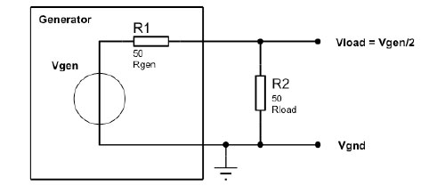
Figure 1. Connecting 50 Ohm equipment forms a voltage divider
If the properties of the load are known, the voltage V_load across it can be calculated with the voltage divider equation from the internal generator voltage V_gen:
V_load = R_load/(R_gen + R_load ) * V_gen (Eq. 1)
Such output/input loading is very important, and should be taken care of in every measurement situation. Fortunately the effect is straightforward, as shown by Equation 1. The caveat is in V_gen. Some manufacturers show on the display of the function generator the voltage Vgen that is generated internally. This is the voltage that you will measure at the output if a high impedance load is used, say an open connection, with a voltmeter or high impedance oscilloscope probe. Other manufacturers expect you to connect a 50 Ohm load. In this case, the display shows the voltage across the 50 Ohm load, with the internal voltage Vgen being twice as high as indicated on the display. If you connect a high impedance voltmeter to such a generator, the measured output voltage is twice that indicated on the display! This is the case e.g with a lot of older HP/Agilent arbitrary waveform and pulse generators. Newer signal generation equipment often offers the user the possibility to set the output for '50 Ohm' or 'High-Z' loads, so that the user can choose between these two modes of indicating Vgen on the display, maximizing the possibility for erroneous readings. Note that the internal 50 Ohm resistor is connected to the generator output irrespective of the mode chosen. The resistor will be there in 'High-Z' mode as well; only the voltage indicated on the display will be changed according to the expected load.
All of this means that the actual output voltage of a generator with a load connected can be 2V_gen, V_gen, or V_gen/2 (or even another fraction) depending on the type of generator used and the impedance of load. It is important to always check the voltage across the load independently, e.g. with a voltmeter or oscilloscope, irrespective of what the signal generator display is saying; this is especially true if you use unfamiliar (or someone else's) equipment. Power supplies typically have negligible output resistance. Here the output voltage on the display corresponds to the voltage across the load, unless the load draws so much current that the current limit of the power supply is reached.
Signal propagation and reflections
The reason why 50 Ohm resistors are used so often is as follows. When a coaxial ('coax') cable is connected to a voltage source V, the output voltage of the source does not instantaneously reach the far end of the cable. How fast the voltage of the source travels down the cable is determined by the speed of light, as the propagating voltage sets up an electromagnetic wave. The propagation speed in the cable is slightly less than the speed of light in free space, by a factor sqrt(epsilon_r), epsilon_r being the dielectric constant of the inner insulation of the cable. As long as the voltage has not reached the far end of the cable, the voltage source is dumping power into the cable to provide the energy to make the voltage V propagate. To provide this power, a current is flowing into the cable too. The amount of current I required determines the 'characteristic impedance' R of the cable. For coax cables this characteristic impedance is a true resistance of typically 50 Ohm (the standard for measurement equipment) or 75 Ohm (the standard for TV cables). This means that as long as the voltage of the voltage source (after we connect the cable) has not traveled to the far end, a current of I = V/R (Ohms' law) will flow into the cable.
Of course, this current will not flow forever, unless the cable is infinitely long. Once the voltage reaches the end of the cable, what will happen depends on what is connected to the far end of the cable. If the cable has a short circuit at the far end, the current will flow through the short and set up a reflected voltage of opposite polarity that cancels the original wave and travels back to the voltage source. If the cable is an open circuit, the reflected wave will reinforce the voltage already present and will temporarily double the voltage on the cable. Both situations give rise to distorted waveforms and can be easily seen when a square wave is sent down a cable while its shape is monitored at the near and far end with an oscilloscope. The faster the edges of the square wave and the higher the frequency of the square wave, the more distorted the square wave becomes. Similarly, under these circumstances, the amplitude of sine waves will be dependent on their frequency.
If however there is a 50 Ohm resistor connected to the far end of the cable, this 50 Ohm resistor looks to the propagating voltage exactly as a 50 Ohm cable of infinite length, and no reflections will occur. The signal stays intact as if it did not encounter the end of the cable; hence the voltage looks exactly as it was at the source. This is the reason for using 50 Ohm output and input resistances: when a matching 50 Ohm cable is used, there will be no reflections, and the signal integrity is preserved up to very high frequencies. The only thing that the cable does is to cause a time delay between when the signal entered the cable, and when it appears on the other side.
There is a very insightful movie made available by BTC Instrumentation, where the cable theory discussed above is demonstrated with a simple experiment (Fig. 2). A function generator is connected to a cable, which has a potentiometer (a variable resistor) at the far end. As the resistor is changed from a short circuit to 50 Ohm to a high resistance, it is easy to see the reflections appear, disappear and then appear again depending on the value of the resistance set by the potentiometer. The movie can be accessed here.
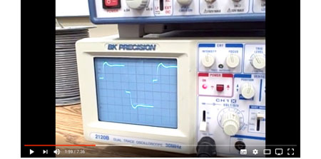
Figure 2. Demonstration of cable reflections
High voltage amplifier input impedance
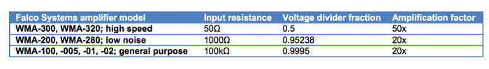
The different Falco Systems high voltage amplifiers have a wide range of input resistance values. These different input resistances present different loading conditions to the generator with its typical 50 Ohm output resistance. The WMA-300 and WMA-320 models are high-speed high voltage amplifiers. They have a 50 Ohm input resistance, as can be expected from their >1MHz maximum operating frequency. The WMA-200 and WMA-280 low noise high voltage amplifiers have a 1kOhm input resistance: these relatively low-valued input resistors exhibit low noise. The general-purpose WMA-100 and WMA-005/-01/-02 high voltage amplifiers have a 100kOhm input resistance and present a negligible load to the generator. The fraction of the voltage set on the generator display that will actually be present across the input of the amplifier can be calculated with Equation 1. It is this fraction (that is available across the amplifier input) that will be amplified by the stated amplification factor of the amplifier! The table shows the fraction of the generator signal available at the amplifier input, assuming a 50 Ohm generator source resistance.
It cannot be stressed enough how important it is to actually measure the signal voltage at the input of a high voltage amplifier before actual use. Fig. 3 shows a simple measurement setup that will yield the input- and output voltages, and is the preferred way to check the amplification factor of the high voltage amplifier.
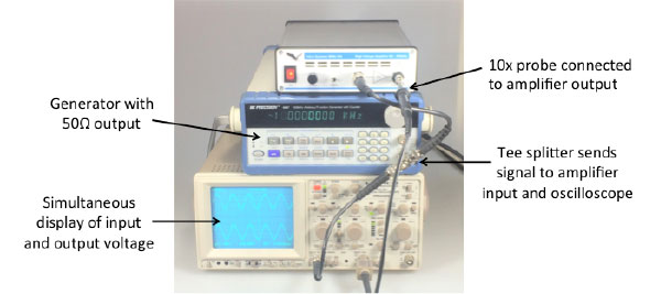
Figure 3. Setup for measuring the high voltage amplifier gain by
simultaneously displaying the input and output voltage of the amplifier
High voltage amplifiers with 50 Ohm (or similar) output resistance
High voltage amplifiers themselves often have an output resistance as well. This resistance is there mostly to prevent overshoot of the amplifier under capacitive loading conditions. Negative feedback is used in these amplifiers to optimize the speed, noise, and amplification accuracy, but will only work well if the output signal of the amplifier is not delayed too much in time compared to the input signal. Capacitive loading of the amplifier output will cause such a time delay. The capacitor needs to be charged by the current flowing into it to change the voltage across it, which takes time. As this time becomes longer with increasing capacitance, the negative feedback loop of the amplifier cannot keep up and overshoots will appear. An output resistor in the amplifier 'decouples' the output of the amplifier from the load, and prevents these overshoots from occurring. The difference can be seen in the behavior of the WMA-200 high voltage amplifier, which has a 50 Ohm output resistor, and the WMA-280, which does not have this resistor, and has an output resistance of nearly 0 Ohm. The effect of capacitive loading on both amplifiers is illustrated in Fig. 4.
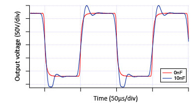
WMA-280 without output resistor
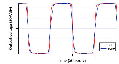
WMA-200 with 50 Ohm output resistor
Figure 4. High voltage amplifier overshoot due to a 10nF capacitor load:
effect of the internal output resistor
Again, the output resistor will form a voltage divider with the load, but as the load of a high voltage amplifier typically has a high impedance, the effect is usually negligible. The output resistor of a high voltage amplifier can be 50 Ohm as this is a value that typically works well, but it does not have to be 50 Ohm.
The resistor is not there to set up a 50 Ohm output - 50 Ohm input system to prevent cable reflections altogether as discussed above. This can be seen from the following. If a WMA-200 high voltage amplifier with its 50 Ohm output resistance and 275mA output current would be used in a 50 Ohm system with a 50 Ohm load connected to the output, the maximum output voltage would be limited by the maximum current to V = I * R = 0.275A * 50 Ohm = 13.75V. This is not useful, as the high voltage amplifier has been specifically designed to provide an output voltage up to 175V. Also the dissipated power in a 50 Ohm load with a high voltage across it would be excessive. A higher load impedance is therefore recommended. For high speed high voltage amplifiers such as the WMA-300 the lack of proper 50 Ohm termination means that cable reflections can and do occur. The cable connected to the output should be as short as reasonably possible. This will make the travelling time in the cable short, and push these reflections to very high frequencies. There is a partial benefit to cable reflections by using a 50 Ohm output resistance for a high voltage amplifier, even though the load is not 50 Ohm. If the coax cable is 50 Ohm and the output resistance of the amplifier is 50 Ohm, the voltage will travel down the cable to the load, be partially reflected, travel back to the amplifier, and will there meet the 50 Ohm resistance of the amplifier again. The reflection will there see a matched 50 Ohm, and not be re-reflected back between the load and the amplifier multiple times, which would cause further degradation of the signal shape. It means that reflections are dissipated by the amplifier after the signal travels in a single pass to the load and back, with no further signal degradation after that. Of course, using a short cable is still important because a single reflection does occur.
Conclusions
Equipment with 50 Ohm input and output resistance is used with matching 50 Ohm cables to provide a reflection-free signal path for the highest signal integrity at high frequencies. It is important to always check the actual voltage amplitudes present in such a system with an oscilloscope. The reason is that e.g. function generators do not have a standardized way of dealing with the voltage drops caused by the 50 Ohm - 50 Ohm voltage dividers created by these resistances. Some voltage sources will display the open circuit voltage, some the voltage in a 50 Ohm load, and this should be checked with all unfamiliar equipment.
High voltage amplifiers also sometimes have a 50 Ohm output resistance, but this resistance is primarily there to prevent overshoot of square wave signals under capacitive loading conditions, caused by the internal negative feedback loop in these amplifiers. A 50 Ohm output resistance here has the advantage that cable reflections damp out in a single pass from the amplifier to the load and back. But it should not be misinterpreted as a standard 50 Ohm output, as the maximum output current is not enough to drive a 50 Ohm load to a high voltage. A higher impedance load is recommended, and, when used with high frequency signals, a short cable from the amplifier to the load is recommended.