High voltage amplifiers - How fast are they really?
Falco Systems application note, version 2.0, March 2016
W. Merlijn van Spengen, PhD
The high speed, high voltage amplifier: performance criteria
High voltage amplifier high speed performance is not only determined by the bandwidth and the slew rate, but also by the maximum sustainable output current of the amplifier and the capacitance of the load. This article discusses the specifications of high voltage amplifiers required to determine whether they are suitable for a certain amplifier-load combination. A corresponding output current calculator can be used to estimate the current and slew rate required to drive a certain capacitive load. It is available here.
The bandwidth
The basic specifications describing the speed of a linear high voltage amplifier such as the Falco Systems WMA-300 are its large signal bandwidth, small signal bandwidth and slew rate. The large signal bandwidth shows what the output amplitude voltage of a high voltage amplifier is for a given input sine wave amplitude as a function of frequency that drives it to its maximum output voltage (Fig. 1). Because the output voltage of the high voltage amplifier falls off gradually above a certain transition frequency, a single magic number named "the bandwidth" being so-and-so many kHz is only useful if also the reduction of the full-power bandwidth of the high voltage amplifier at this frequency is also quoted. It is often expressed as the -3dB point, where the amplitude has fallen to 0.707 times the maximum amplitude at low frequencies, but this is not always the way it is specified, so one has to be careful with a single number. A graph showing the maximum output voltage versus frequency conveys much more information. The small-signal bandwidth (sometimes also called "the bandwidth") is the frequency response of the high voltage amplifier at some very low output voltage like 1% of the maximum output. This bandwidth is usually larger than the large signal bandwidth by a significant amount.
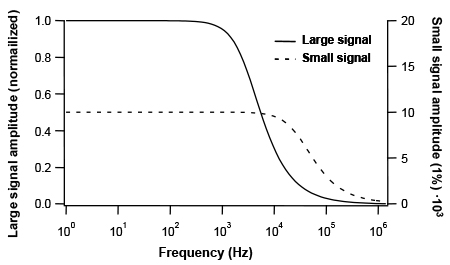
Figure 1. The large signal and small signal bandwidth of a high voltage amplifier can differ significantly
The step response and the slew rate
The step response is the time an amplifier needs to go from 10% to 90% of the total output voltage in response to a step in voltage at the input (Fig. 2). The corresponding slew rate of a high voltage amplifier is a fairly subtle spec. It is the fastest voltage change that the output can make, and as such it is the slope of the fastest part of the curve in Fig 2. It is given in V/us, the number of volts that the output can rise (or fall) in one microsecond, if it could continue to rise for one microsecond. This spec obviously limits the capability of an amplifier to generate high voltage pulses with sharp rising and falling edges (Fig. 3), but is also a bandwidth limiting factor for sine-wave or arbitrary signals. This can be seen as follows. The highest rate of change in the output voltage of a sine wave is at the 0V-crossing (Fig. 4). The higher the frequency, the faster the voltage has to rise there to prevent distortion of the sine wave. If the high voltage amplifier cannot follow due to its limited slew rate, the sine wave will be distorted to a triangle, and its amplitude is lower than at low frequencies. The maximum peak to peak sine wave output voltage Vpp is related to the slew rate S by Vpp = S/(pi*f), where f is the frequency of the sine wave. Note that this is at full amplitude, not at -3dB.
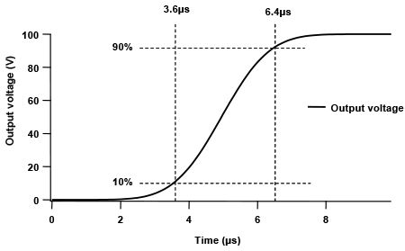
Figure 2. The step response of a high voltage amplifier is the time required to change the output from 10% to 90% amplitude. In this example the slew rate (the fastest rise of the curve) can be conservatively estimated to be 80V/2.8us = 29V/us based on the step response. In fact, the slew rate is a little higher than calculated, as the fastest rise (in the middle) is higher than that of the full 10 - 90% transition.
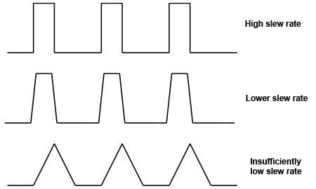
Figure 3. Depending on the slew rate of the amplifier, a set of pulses can either be amplified undistorted or severely affected.
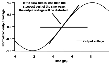
Figure 4. If the slew rate of the amplifier is not sufficient sine waves are distorted as well. The higher the frequency and the amplitude of the waveform, the more important is the slew rate of the high voltage amplifier.
Slew rate versus current - capacitive loading
The discussion above assumed that the load at the output of the high voltage amplifier does not influence the behavior of the amplifier in any way. This is the case for very small capacitive or resistive loads. However, typical loads for a high voltage amplifier are highly capacitive, like PZT (piezo) transducers, EO (Electro-Optical) modulators, and, to a lesser extent, coaxial cables (a RG58 cable constitutes about 100pF per meter!). To be able to bring the output voltage of the high voltage amplifier to a certain level, this component at the output (representing electronically a capacitor) has to be charged to this voltage (Fig. 5). If the high voltage amplifier has a current limit of IL amperes, it can charge up a capacitor C only with a certain maximum speed. The maximum rise in voltage per microsecond (again a slew rate, but now determined by the maximum current and the load capacitor, so we call it SA) is then SA = IL/C, which can for large capacitance values be significantly lower than the intrinsic slew rate of the amplifier S discussed above. The bandwidth for sine wave signals is reduced correspondingly. Even worse: if the high voltage amplifier has a current limit but will overheat when the maximum current is drawn continuously, it will break down or (preferably) shut down after a while when delivering a high frequency, high voltage output, even though the load at low frequencies is negligible. This is a real problem with amplifiers that have a high peak output current, but a much lower maximum average current specification.
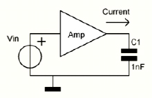
Figure 5. A capacitive load at the output of the high voltage amplifier can change its slew rate
Instabilities and overshoot due to capacitive loading
Many high voltage amplifiers have an internal circuitry that looks like a high voltage version of the general operational amplifier (opamp, Fig. 6). A capacitor at the output of such a circuit in combination with the opamp output resistance creates a time lag of the output voltage, because the capacitor has to be charged first as discussed above. This means that the voltage at the (-) input of the opamp is delayed too, which can cause the signal at the (+) and (-) input at certain frequencies to be 180 degrees out of phase rather than in-phase. If this happens with certain capacitance value at frequencies well above the frequency where the opamp has an amplification smaller than 1, this is no problem, but when this happens at a frequency where the opamp is still capable of amplifying the signal, the circuit has been effectively turned into an oscillator. The result is then at least overshoot or ringing at the output, and in extreme cases sporadic or continuous oscillations (Fig. 7). If the capacitor value is chosen large enough, this effect disappears again (although with a dramatically reduced bandwidth as a result). This means that many amplifiers have a certain capacitive load value where they are most likely to generate spurious signals. Only by placing the output stage outside the feedback loop (Fig. 8) in a high voltage amplifier design, this effect is circumvented.
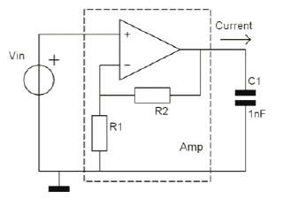
Figure 6. Most high voltage amplifiers have an internal structure that is similar to that of an operational amplifier. Certain load capacitance values can cause instability of the amplifier
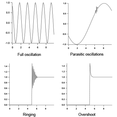
Figure 7. Amplifier instability manifests itself in various ways on the oscilloscope
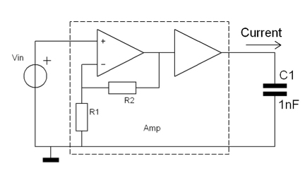
Figure 8. By adding an independent output stage that is not in the feedback loop, the instabilities of a conventional high voltage amplifier at certain capacitive loading conditions are eliminated
Example with numbers, using the Falco Systems WMA-300 high speed, high voltage amplifier
In the following section, we illustrate the principles discussed above by comparing them to specs of a real high voltage amplifier, the Falco Systems WMA-300 (Fig. 9). It is made for very high speed operation and hence has a very large power bandwidth of DC - 5 MHz (-3dB) and a 2000V/us slew rate. The main application is in MEMS (micro-electromechanical systems) or EO-modulators, where the connecting coax cables are usually the main capacitive load (~100pF), but it is instructive to see what happens when the capacitive load is increased to the values typical for piezo-transducers (~nF). The large signal bandwidth of the WMA-300 with 300Vpp output voltage (the maximum) is given in Fig. 10. The slew rate is measured by monitoring the rise-time of a pulse on an oscilloscope (Fig. 11). The bandwidth and slew rate specs result in a nice 300Vpp 100kHz square wave (Fig.12) with fast rising and falling edges with no load. This waveform is distorted if we add a significant load capacitance (Fig. 13). For 150pF the effect is negligible, but when we drive several nanofarads, the speed is reduced considerably. The reason is the 300mA current limit of the WMA-300 that limits the speed at which the capacitor can be charged, and hence the loaded slew rate SA is smaller for the loaded conditions. Note that there is no capacitive load at which the system generates overshoot. Unlike in many other amplifiers, in the WMA-300 the configuration of Fig. 8 has been used, which effectively prevents any instability caused by the load.
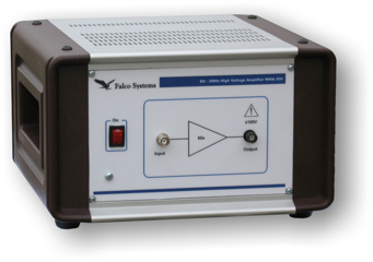
Figure 9. A wide bandwidth high voltage amplifier, The Falco Systems WMA-300
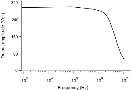
Figure 10.The large signal bandwidth of the WMA-300
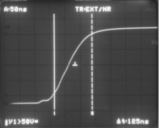
Figure 11.The slew rate of the WMA-300 is obtained by investigating the step response time it takes for a voltage pulse from -150 to +150V to go from 10% to 90% amplitude. On the oscilloscope screen the 0%, 10%, 90% and 100% marks on the left are used to do the measurement properly. 240V in 125ns gives a conservative estimate of 1920V/us.
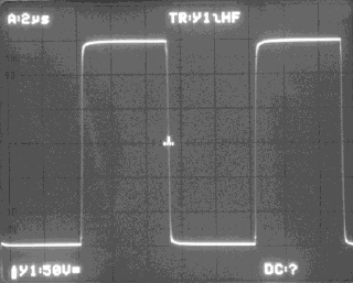
Figure 12. An oscilloscope image of an amplified, undistorted 100kHz, 300Vpp square wave with no load at the output of the high voltage amplifier
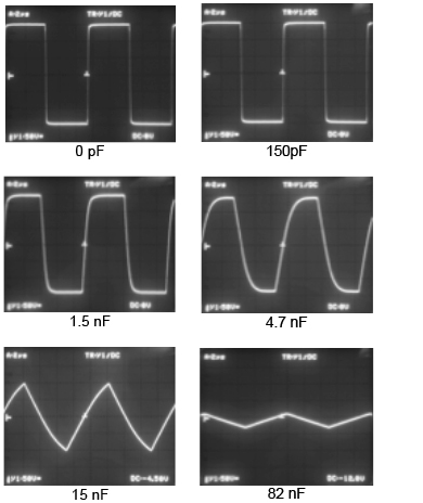
Figure 13. Loading the high voltage amplifier with different capacitors at its output limits the slew rate
Conclusions
To select a high speed high voltage amplifier for a certain purpose, one has to look not only at the bandwidth and/or slew rate of the amplifier, but also at the expected capacitive load, the maximum sustainable output current (as opposed to peak current) and the possibility of instability and overshoot voltages damaging the load. Control over all of these is required for an optimal result.